|
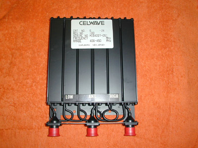
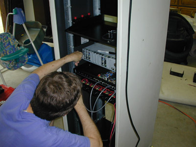
This is Marshall (KE6PCV) me, drilling a 4 inch hole in a rack tray.
This 4 inch hole will be where the cooling fan is mounted for the link
transmitter.
|
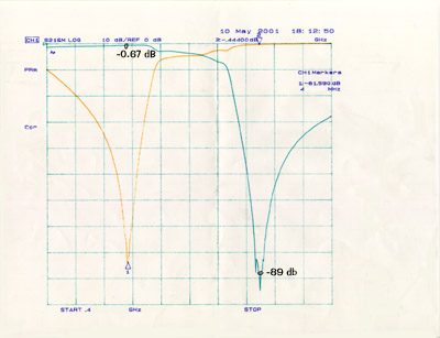
Another shot of the
special 4 inch drill bit that we use to make holes in metal for the
cooling fans. This drill bit is a very expensive tool! But it sure makes
the holes come out nice and even in the metal. It nice to have the
right tools!
|
|
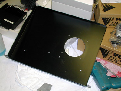
Here is what the rack tray looks like when we get done drilling the
necessary holes for the fan and link radio brackets.
|
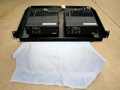
A front view of the finished link radio tray. Bob
(WB6DIJ) bought these radios for the Otay project. Bob also
modified these radios and installed DB9 connectors onto the back of each
radio. Thanks Bob!
|
|
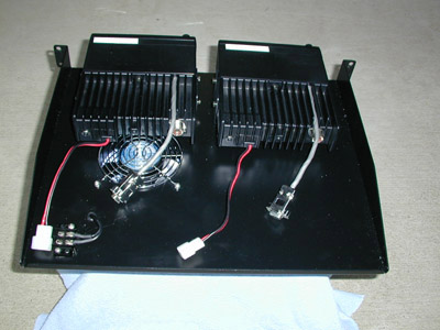
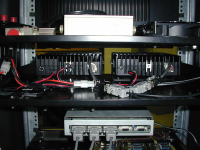
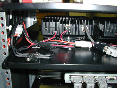
This is a back view if the link radio tray. This tray mounts right into
the repeater rack. One radio for receive and one radio for transmit.
This allows Calnet to run full duplex on our links. Notice the DB9
connectors that Bob (WB6DIJ) installed on the radios. These connectors
allow us to access discriminator audio, PTT and transmit audio from
inside the radio.
|
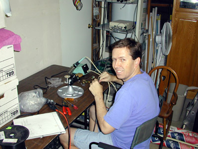
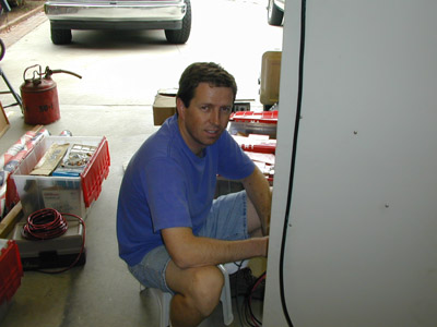
Gerry (KB6OOC), came of to the house and helped out
by building the DB9 cables that go from the controller to the UAB box.
He also built the DB9 cables that go from the Mitrek head plugs to the
back of the UAB box. I think that he built a total of 9 cables. He
started at 4:00 pm and he did not finish until 10:00 pm. Lots of labor
involved!
|
|
Gerry (KB6OOC) plugging in one of the custom DB9 cables that he made
into the controller. Each cable was cut to the right length then built.
|
Another shot of Gerry as he is working on the cabling
for the UAB box and the Controller.
|
|
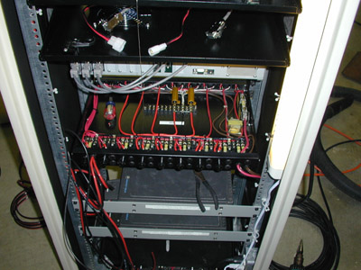
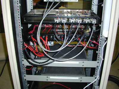
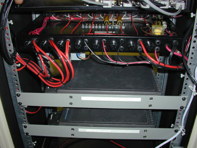
This is a view of the back of the rack looking down on the DC power
switch box built by Cliff (KA6JRG). Below the power box are the Mitrek
radios that are mounted on rack panels.
|
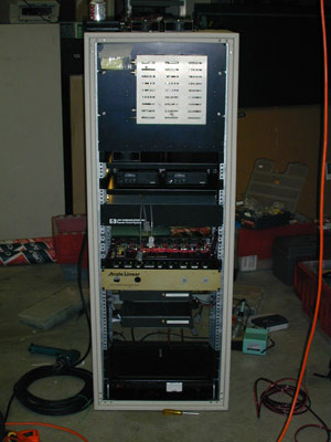
Finally a view of the rack at 10:30 pm. We spent a
lot of time today working on the project and got a great deal of work
accomplished. The rack is starting to look like a real Calnet repeater!
|