Otay Repeater Project
|
May 4th 2001 Progress |
|
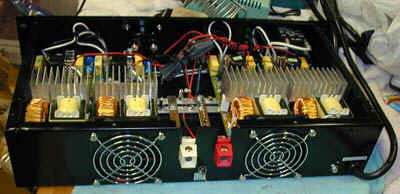
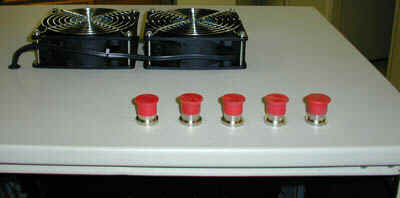
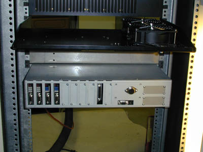
This is the new Samlex switching power supply. Notice
the four 20 amp modules installed in this unit. This will give us 80 amps continuous
DC power in the rack. |
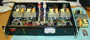
Here is a front view of the new power supply. Notice the space in the middle of the power supply. If we need extra amperage we can add one additional power module for a total of 100 amps continuous power. |
|
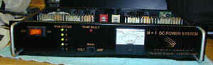
Here is a front view of the new switching power supply for Otay. This is about half the size and weight of an Astron power supply. We need this smaller size supply because of space limitations in our repeater rack. We are going to have a ton of stuff in this rack with only 5 vertical feet of rack space. |
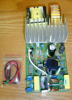
This is a picture of a separate 20 amp module for the
power supply. If one of these modules in the switching power supply should
fail, the other units in the supply will share the load of the current
demands. I ordered and extra module to have on hand to make hilltop
repairs easy. Just replace the module and we are back to normal. |
|
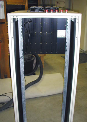
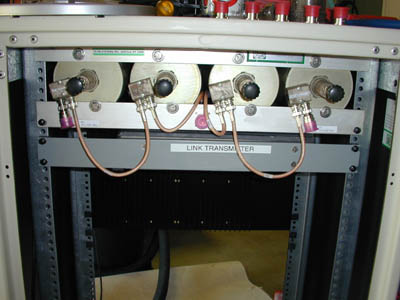
This is a TE Systems amplifier looking form the back side of the rack. This will be used for the repeater output. This sucker is huge and should just purr putting out 75 watts. <GRIN> |
This is the TE Systems amp looking form the front side of the rack.
|
|
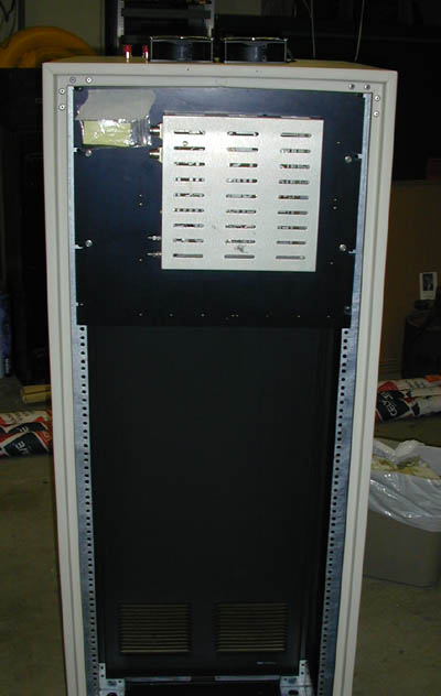
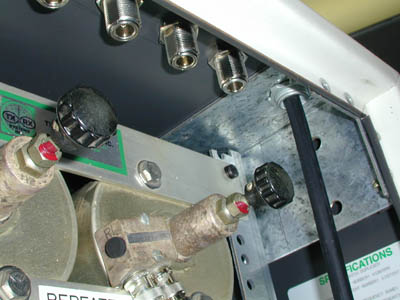
This picture was taken form the rear top side of the rack. Notice that there are 5 N-male feed through connectors. We should only need 4 connectors, but I added an extra one just incase. You never know when we might need that extra connection on the top of the rack. Its easier to do it now, than later!
|
This is a close up of the rubber grummet on the top of the rack that feeds AC power form inside the rack to the high volume ventilation fans on the top of the rack. |
|
|
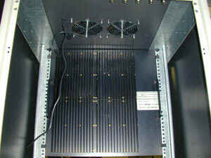
This is the view of the rack looking form the back of the rack up to the top of the rack. Notice the huge heat sink fins for the repeater amplifier. Also notice the cooling fans have finger guards on the inside as well as the outside of the rack. We have learned from experience that it is a good idea to spend the few extra bucks and install guards on the inside. Its real easy to stick your finger in one of these fans when they are running. Just ask Gerry, Cliff or myself. Unfortunately we all know first hand (finger) !! <GRIN> So far I have about 7 hours of labor into this project. Drilling holes,
installing fans, installing bulkhead feed through N-connectors and re-mounting
the rack rails inside the cabinet. Building a repeater for a linked
system takes lots of time! 73 Marshall - ke6pcv
|
|
May 5th 2001 Progress |
|
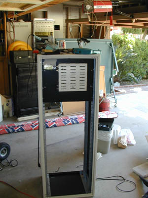
This is what the rack looked like this morning when I
started out today. |
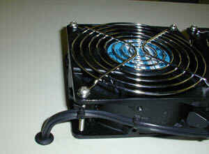
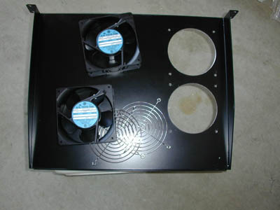
This is a transmitter fan tray. This will be mounted directly underneath all the transmitter cooling fins. These holes are manually drilled into this shelf. Then we mount the fans onto the shelf with stainless steal hardware and finger guards. |
|
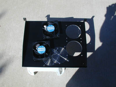
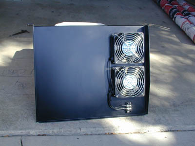
Here is another shot of the cooling fan tray before it
gets put together. Notice that we use 2 high volume fans instead of one. There is a reason
why Calnet uses two fans. In the event that we have a
failure to one of these fans the second fan will act as a backup and still
keep the transmitters nice and cool. This is the Calnet system standard
that we use on all our repeaters. |
This is the top of the rack with the repeater TX/RX
duplexer installed backwards in the rack. Notice the extra rack rails
installed on the back of the rack. I add an additional set of rack rails
so that we could install equipment on both sides of the rack. We are
trying to use every last bit of space. |
|
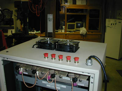
Here is a snapshot of the finished product of the fan tray. These fans will be actuated on and off by a thermostatic controlled switch mounted on the heat sink of the transmitter. |
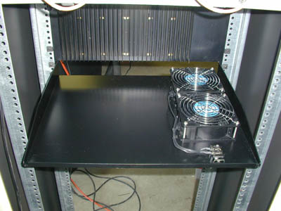
This is the fan tray installed in the rack. The
repeater and link transmitters will be installed directly above these
fans. Notice that these fans will also help cool the repeater amplifier.
These fans are high CFM output fans. |
|
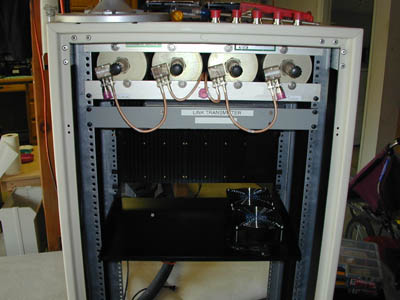
This view shows the top half of the rack. I
installed a transmitter radio just below the duplexer to get a basic idea
of the spacing in the rack. |
This picture is a close up of the top of the rack looking
upwards from the rear of the rack. Notice the new AC power cord on the
right hand side of the photo. This cord will supply AC power to the rack. |
|
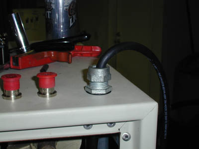
A top view of the rear of corner showing the AC power cord going
through the water tight grommet. |
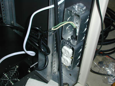
Bottom rear right hand corner of the rack showing the AC
power plugs that will power up various items in the rack. Nothing is plug an
play when it comes to building a repeater. All these things have to be made by hand,
just the way we want. It
all takes TIME! |
|
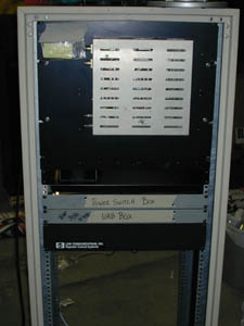
Front view of the rack from top to bottom. TE systems
amp, (dummy panel to line up spacing in the rack, Cliff, KA6JRG is working
on this DC power switch box and should be done in a week or so), (dummy
panel Gerry, KB6OOC is working on the UAB box and should be done in a week
or so) and RLC-3 controller. |
This is the back of the rack looking at the new Link
Communications RLC-3 Control System. It is a really nice piece of
hardware. Probably the best control system money can buy! <GRIN> |
|
Top of the rack with a few need additions. |
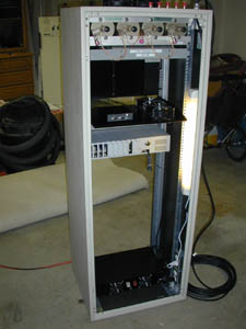
Here is a shot of the back of the rack from top to
bottom. Notice the new fluorescent light on the right hand side of the
rack. This extra lighting will come in real handy when we are up at Otay
and need to see the UAB box and controller to set audio levels. |
|
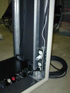
This is the bottom right rear of the repeater rack with
the finished up AC power plugs. Also notice the new Samlex DC power supply
installed on the bottom of this picture. |
Well today was a very productive day and much headway was
made in the construction of the new Otay repeater. I spent a total
of about 9 hours on the project today. I can't wait to get some more
of the needed parts to install in the rack. Its coming along quite
nicely.
73! Marshall - ke6pcv |
Map | Registration |
Audio | Bios
Home | Photo | FAQ | Email
Copyright © 2009 Calnet Web Design & Host
Last Updated
July 12, 2020
Author ke6pcv@cal-net.org